The Demon Core · Volume 2
The Demon Core: Replica build
Introduction
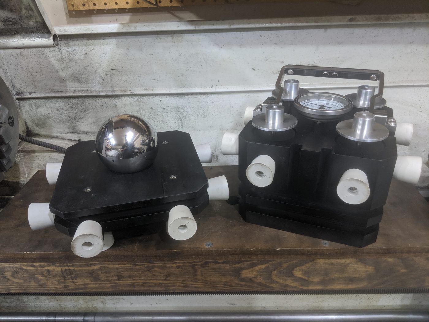
This volume is the practical companion to Vol 1’s history. It documents a museum-quality, non-functional replica build pair of two objects: (a) the demon core itself — a 3.5 inch (89 mm) tungsten-heavy-alloy sphere, bisected on the equator and hollowed at the center to receive (b) a hand-machined replica of the Po-Be “Urchin” initiator that the original pit cradled in its 25-millimeter inner cavity; and (c) two reproductions of the Manhattan-Project plutonium carrying box that Philip Morrison designed and Ralph C. Sparks machined at Los Alamos in 1945 — one in the black-crackle Trinity-gadget-core finish that Adam Savage milled on the 2024 Tested one-day build, and one in the zinc-chromate yellow Fat-Man finish that Harold Agnew is carrying in the famous 1945 Tinian photograph.
The replica pair targets museum-fidelity. Everything visible from a meter away matches the original geometry and finish. Everything inside that you can hold matches the original mass to within 50 grams. Nothing here is fissile or radioactive in any way; the sphere is a tungsten-alloy stand-in (W90/Ni7/Fe3 at 17 g/cm³, dense enough to hit the original 6.2 kg target), the Urchin replica is brass and aluminum, and the box bodies are Richlite phenolic-paper laminate. The total build runs about $2,000 in materials and three to four weekends of shop time across two boxes.
The plan is built from four sources, listed in descending order of importance: the 2024 Tested YouTube episode “Adam Savage Builds a Demon Core!” (transcript on file at 02-inputs/Adam Savage Youtube Build Transcript.txt); Alex Wellerstein’s “The plutonium box” essay on Restricted Data (2014); Ralph C. Sparks’s memoir Twilight Time (LAHS, 2000); and the Wikipedia Urchin (detonator) article and Granowitz’s 2024 Stanford PH241 paper for pit and initiator dimensions. Where the build deviates from these references the deviation is flagged in the prose.
2.1 §1 What we’re matching, and what we’re not
The originals were three magnesium boxes machined to about ±0.005 inch tolerances by a working machinist on production equipment. The Trinity gadget-core box was left raw and chemical-etched to a dull black. The Fat-Man box that traveled to Tinian was painted with zinc-chromate yellow anti-corrosion primer for visibility through tropical humidity. A third box was built for the never-dropped third pit — the demon core itself — but the only surviving photograph of it is black-and-white, so we cannot say with certainty whether it was yellow or black. Building one of each finish hedges that question and produces two complete display pieces.
Table 1 — §1 What we're matching, and what we're not
| Aspect | Original (1945) | Adam Savage (Tested, 2024) | This build |
|---|---|---|---|
| Body material | Magnesium plate | Richlite phenolic-paper laminate | Richlite phenolic-paper laminate |
| Body construction | Machined from solid | Four 8″×8″×2″ slabs epoxy-laminated, then face-milled | Same |
| Exterior dimension | 7-1/4 inch cube | 7-1/4 inch cube | 7-1/4 inch cube |
| Split line | One-third up from bottom | One-third up from bottom | One-third up from bottom |
| Sphere cradle | ~4/5 in bottom, 1/5 in top | 4/5 / 1/5 split (you can lift the ball out) | 4/5 / 1/5 split |
| Hardware | Four perimeter through-bolts | Four counter-sunk 1/4-20 cap screws with Helicoil inserts | Same |
| Urchin ports | Four threaded ports on top, holding the initiators | Four aluminum plug-and-ring assemblies, internal 2-3/8″ thread | Same |
| Thermometer | Top-dead-center process dial in 1/2″ NPT boss | Same | Same |
| Handle | Bent aluminum bar with shaped sub-grip | Aluminum bar + Delrin scales, brass alignment pins | Same |
| Bumpers | Rubber test-tube stoppers, 20 around the box | Black rubber pucks, 20 around the box | Rubber stoppers, 20 around the box |
| Finish | Black chem-etch (Trinity) or yellow zinc-chromate (Fat Man) | PJ1 Fast Black wrinkle paint, baked | One box black crackle; one box zinc-chromate-style yellow |
| Core | 6.2 kg Pu-Ga alloy, 89 mm Ø, nickel-plated, hollow centered 25 mm cavity for the Urchin | Solid tungsten-alloy sphere, 89 mm Ø, ~6.25 kg, no internal cavity | Bisected tungsten-alloy sphere, 89 mm Ø, ~6.25 kg, 25 mm interior cavity with replica Urchin |
| Initiator | Po-210 / beryllium “Urchin,” 20 mm Ø Be shell, 8 mm Po-coated Ni-plated pellet, ~7 g, gold + Ni finish | Not modeled | Hand-fabricated 20 mm brass replica, gold-toned, 15 wedge grooves on inner mating surfaces |
The only deviation from “Adam’s exact method” is the bisected pit with the working Urchin cavity. Adam left his sphere whole and noted in the closing monologue that the originals were “cleaved in twain right up the equator and they had a void in the middle.” Our build closes that gap.

2.2 §2 The pit — bisected tungsten-alloy sphere
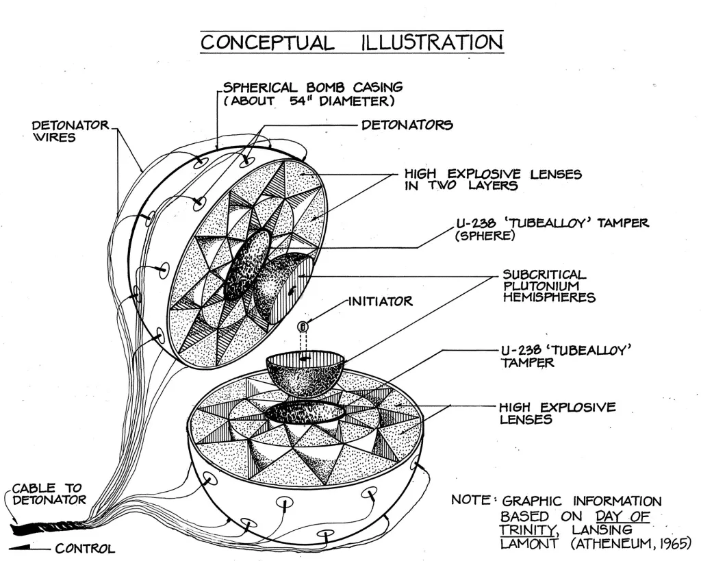
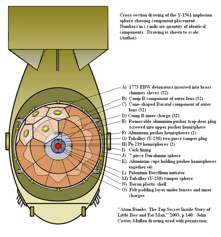
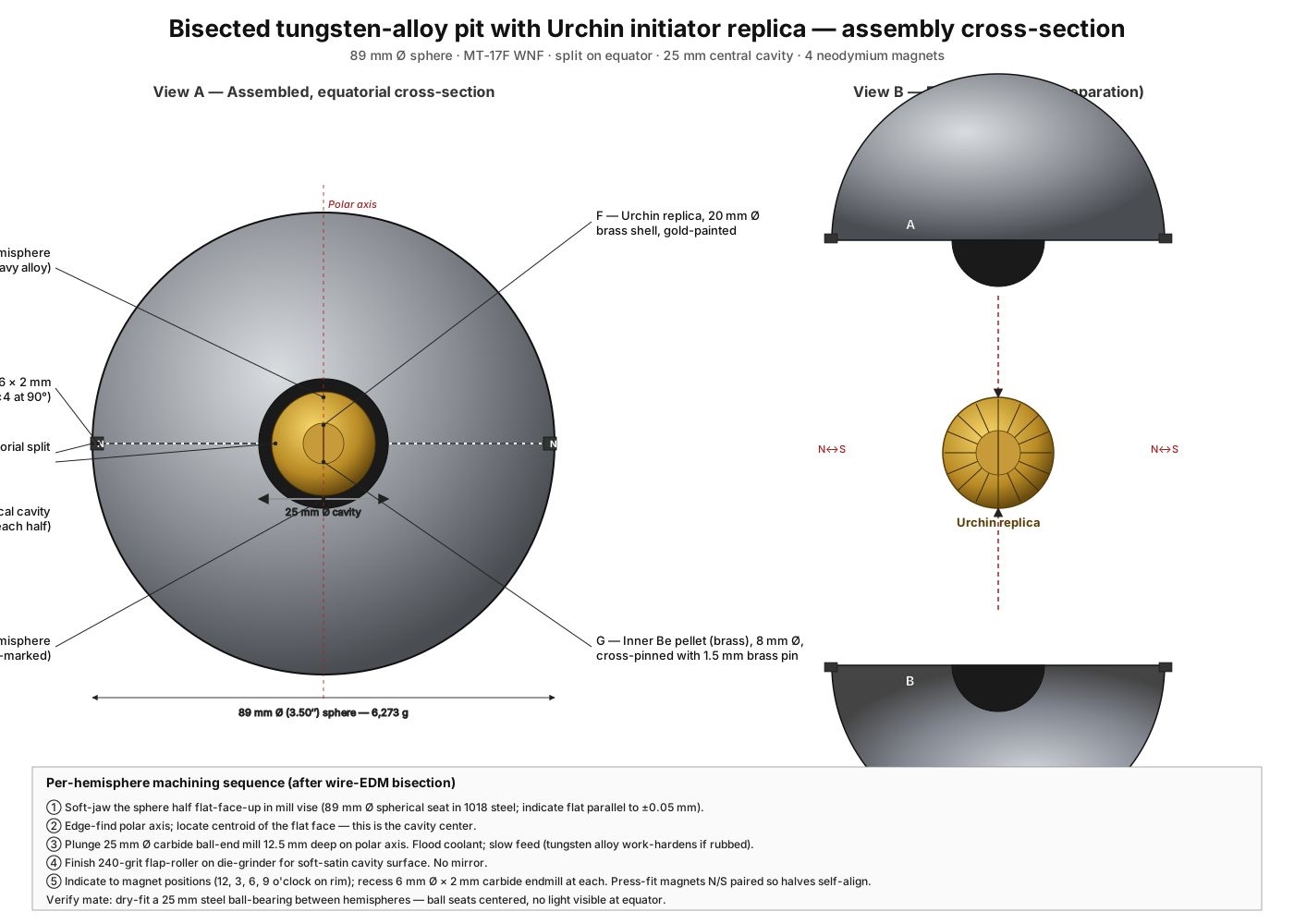
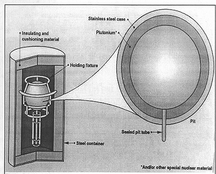
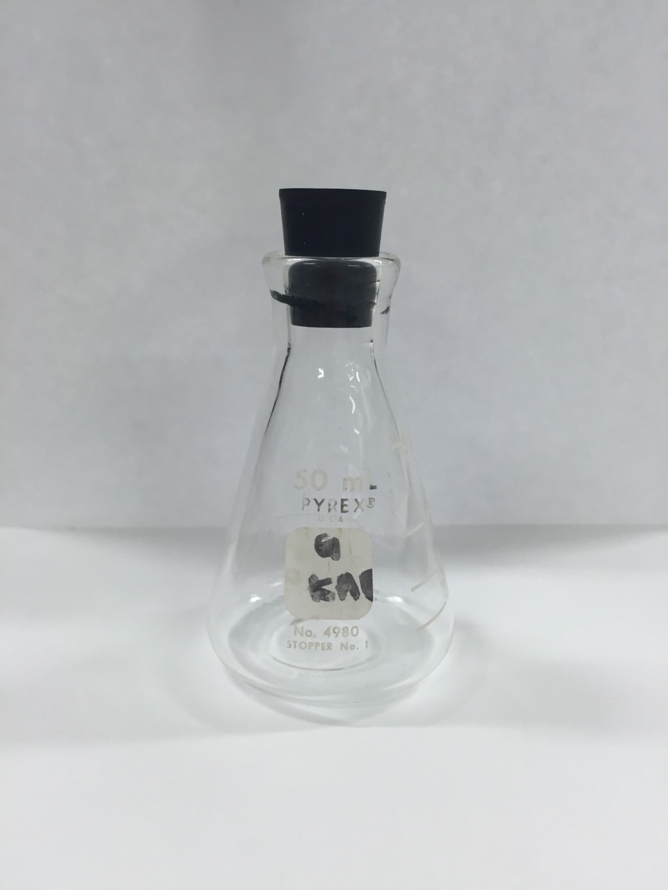
The original demon core was 89 millimeters (3.5 inches) in diameter and 6.2 kilograms (~14 pounds) of δ-phase plutonium-gallium alloy, hot-pressed and nickel-coated, formed as two hemispheres around a 25 mm hollow centered on the polar axis. When the pit was assembled into a bomb the central cavity received the Po-Be Urchin initiator; when the pit was in transport the cavity was usually empty and the Urchin was stored separately in one of the four threaded ports on top of the box (more on those in §5).
2.2.1 §2.1 Sphere sourcing
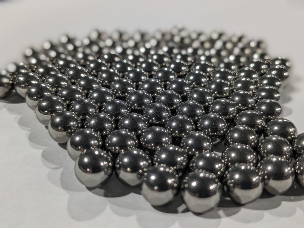
The build uses a single 3.5 inch (89 mm) diameter custom-order tungsten heavy-alloy sphere from Midwest Tungsten Service, alloy designation MT-17F WNF — 90% tungsten, 7% nickel, 3% iron by weight, ~17 g/cm³, hardness HRC 25, mercury-free. This is the alloy Adam Savage’s certification card identifies as MT-17F9 WNF in the Tested video. MT’s standard catalog does not list a 3.5 inch sphere (the closest stocked sizes are 2.75 inch and 4 inch), so this requires a custom-quote order; expect $1,200–$1,500 and a six-to-eight week lead time.
A sphere of 89.0 mm diameter at 17.0 g/cm³ computes to:
- Volume = (4/3) × π × (44.50 mm)³ = 369.0 cm³
- Mass = 369.0 cm³ × 17.0 g/cm³ = 6,273 g ≈ 6.27 kg ≈ 13.83 lb
— within 73 g (1.2%) of the demon core’s stated 6.2 kg. The match is closer than any other off-the-shelf metal at the same volume. Lead at 11.3 g/cm³ would yield only 4.17 kg; depleted uranium would overshoot at 6.96 kg and is unobtainable for hobby use; pure tungsten at 19.3 g/cm³ would overshoot at 7.12 kg and is essentially un-machinable.
Why this alloy specifically:
- The 7% Ni / 3% Fe content lowers tungsten’s intrinsic brittleness to a workable HRC 25 — comparable to mild steel. The alloy can be bored, sawn, turned, milled, ground, lapped, and EDM-cut with conventional carbide tooling and bi-metal blades. Pure tungsten cannot.
- The dull silver-grey surface that comes off MT’s centerless grinder reads as nickel plate at conversational distance. No surface finish is strictly necessary.
- Tungsten alloy at this composition is genuinely non-hazardous: not radioactive, not pyrophoric (unlike pure tungsten dust), not on the RoHS restricted list. Standard machinist PPE is sufficient.
Order specifications to send to MT: 3.500″ ± 0.005″ diameter, MT-17F WNF, finish “as-ground” (about 32 µin Ra), mercury-free certification, ship via UPS Ground in a fitted foam-lined box. Reference Adam Savage’s certificate of compliance (visible on screen at 3:32 in the Tested episode) as the format expected.
2.2.2 §2.2 Equatorial bisection
The sphere needs to be split exactly on a great circle through the center. There are three practical paths; only one is recommended.
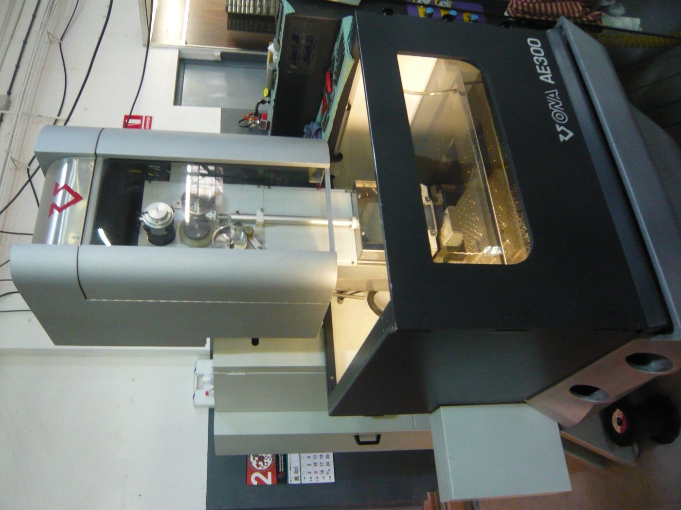
Path A (recommended) — Send-out wire EDM. Ship the sphere to a local job shop with a wire EDM machine and fixture it in a custom-machined V-block cradle (a $20 piece of 6061 aluminum, drilled to clamp the sphere at a known center height). The wire — typically 0.010″ brass — passes through the sphere along the equator in a single straight cut. Kerf is about 0.25 mm, finish is mirror-smooth and requires no lapping. Total send-out cost runs $200–$300 depending on shop rates; turnaround is typically one to three working days. This is the only path that protects the sphere’s value. A botched cut in either of the alternates ruins a $1,500 part.
Path B — Horizontal bandsaw with bi-metal blade. A serious horizontal bandsaw (Wells-Index or similar, not a benchtop) with a 6 tpi bi-metal blade will cut the sphere, but slowly — expect 45 minutes for the cut, with frequent coolant flooding to keep the blade from glazing. Kerf is wide (~1.5 mm) and the cut faces will need substantial flat-lapping afterward to mate cleanly. Acceptable if you already own the saw and want the experience; not recommended if you do not.
Path C — Lathe parting. Possible but not recommended. The sphere has to be held in a 4-jaw chuck with extreme care (a tungsten sphere with a finished surface and a slip-out trajectory toward the operator’s chest is a memorable hazard), and the parting tool will work-harden the alloy as it goes. Skip.
After the cut, mark the two hemispheres with a small letter punch on the back of the rim — “A” and “B” — so they return to their original mating orientation every time.
2.2.3 §2.3 Urchin cavity machining
On the flat-face side of each hemisphere, a 12.5 mm-deep × 25 mm-Ø half-spherical pocket has to be machined on the polar axis. When the two halves close on their equator, the pockets mate into a true 25 mm spherical void at the geometric center of the sphere — the Urchin’s home. (Wellerstein and the Urchin Wikipedia article both cite a 1-inch / 25 mm inner cavity in the original pit, with the 20 mm Urchin held by spring brackets in that void.)
Procedure on a vertical mill:
- Make a pair of soft jaws for the mill vise, machined with a 89 mm-diameter half-spherical seat. Standard 1018 steel; CNC the seats if you have one, or hand-scrape to the sphere itself if you don’t. The seats need to grip without marking.
- Clamp a hemisphere flat-face-up in the jaws. Check that the flat face is parallel to the table to within 0.05 mm with an indicator on the highest point of the rim; shim if needed.
- Locate the pole — the polar axis is perpendicular to the flat face and passes through its centroid. Use an edge finder against the rim to find the centroid; double-check by indicating the flat face’s geometric center.
- Plunge a 25 mm Ø carbide ball-end mill (or a 1/2″ ball-end and orbital-milled to 25 mm radius) to a Z-depth of 12.5 mm below the flat face. Feed slowly — tungsten alloy work-hardens if rubbed. Flood coolant.
- Surface-finish the cavity at 240 grit with abrasive flap-roller on a die grinder. Aim for a soft satin, not mirror.
Repeat for the other hemisphere. Verify the two cavities mate into a true 25 mm sphere by dry-fitting a 25 mm steel ball-bearing between them — the bearing should sit centered with the halves closed and no light visible at the equator.
2.2.4 §2.4 Hold-together hardware
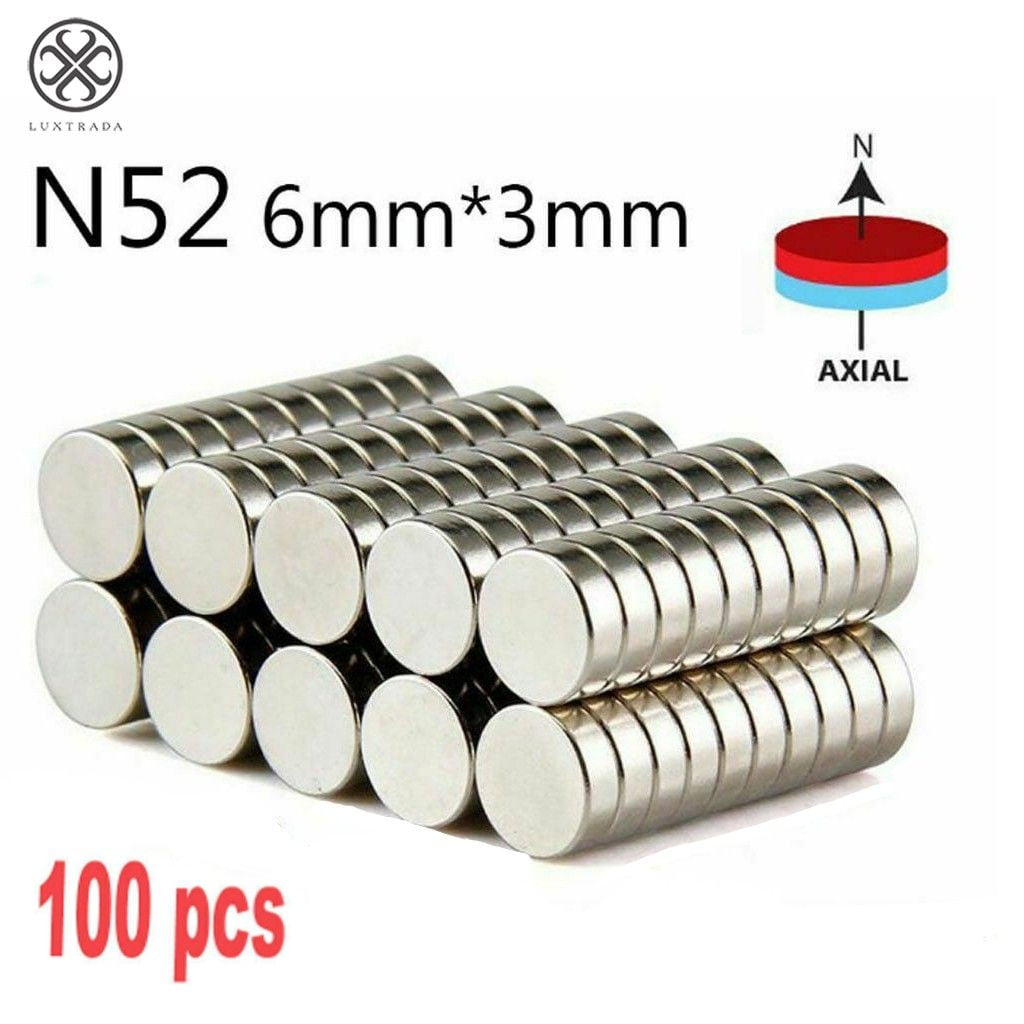
The two halves of the sphere are held together by four 6 mm Ø × 2 mm thick neodymium disc magnets, two per hemisphere, recessed flush into the equatorial flat at 90° intervals (12, 3, 6, 9 o’clock). Magnets are paired N-up / S-up so the hemispheres self-align on closure. Pull force per pair is about 3 kg; total ~12 kg, enough to keep the seam tight under normal handling but easily broken by hand for opening.
Recess the magnets with a 6 mm carbide endmill at 2 mm depth from the equatorial flat. Press-fit (no glue needed — the recess depth is 0.1 mm less than the magnet thickness so the magnets sit proud by 0.1 mm, ensuring metal-on-metal contact between halves with no air gap). If a magnet has to be removed later, a 4 mm steel rod through the cavity pushes it out.
2.2.5 §2.5 Surface finish — leave it, or send it for nickel plating?
The default is as-machined: the centerless-ground surface that MT delivers reads as nickel plate at a meter, and the build leaves it untouched. This is Adam’s path and it’s the simpler one.
For the absolutist finish, send out for electroless nickel plating after the bisection and cavity work are complete. Electroless nickel deposits an even 10–25 µm coating of ~88% Ni / 12% P alloy by chemical reduction (no electrode wires touching the surface, so the geometry is preserved exactly). The result is a brighter, more uniform silver-white that closely matches what the original pit looked like in the LANL recreation photographs. Cost: $75–$150 at any local plating shop; turnaround a few working days.
Why we don’t do it by default. The plating step has to happen after the bisection and the magnet recesses, because plating fills features and the magnets need bare-metal contact. That means handling a $1,500 part through one more process step with one more shop. The as-machined finish is good enough to not be the visual weak link; the plating is an upgrade for a future revision if the build calls out for it.
2.3 §3 The Urchin replica
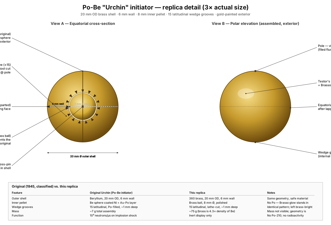
The original Urchin was a 20 mm-diameter beryllium shell, 6 mm thick, with 15 concentric wedge-shaped grooves cut into its inner surface. Inside the shell sat an 8 mm-diameter beryllium sphere coated with gold and nickel, and a thin layer of polonium-210 (about 11 mg, 50 curies) was deposited in the grooves and on the inner sphere. The whole assembly weighed ~7 grams and was held in the pit’s 25 mm central cavity by spring brackets. When the implosion shock wave struck the assembly the wedge grooves disrupted, the polonium mixed with the beryllium, and the alpha-on-Be reaction released ~10^9 neutrons in under a microsecond — the timing kick that started the chain reaction.
The replica does not need to function. It needs to look right when nested in the bisected pit with the lid lifted.
Procedure:
- Outer shell. Turn a 20 mm-diameter brass sphere on the lathe from 25 mm 360-brass rod. Part it off, chuck the half-finished sphere in a collet, finish-turn to size. Polish to 600 grit.
- Equatorial bisection. Split the sphere on a great circle (a lathe parting tool works fine here — brass parts cleanly, unlike tungsten). Two hemispheres, mating face flat.
- Wedge grooves. On the flat mating face of each hemisphere, scribe 15 latitudinal wedge grooves with the lathe set up for spiral cutting — set up the half in a 5C collet with a known datum, single-point the grooves with a 60° threading tool, 1 mm deep at the equator and tapering to 0 at the inner edge. Same on the other hemisphere.
- Central pellet. Turn an 8 mm-diameter brass ball from the same stock. Drill a 1.5 mm bore for a brass pin that holds it centered in the shell.
- Pin and assemble. Cross-drill the two hemispheres at their poles for a 1.5 mm brass pin; the central ball threads onto that pin, halves close around it. Light epoxy on the pin holds the assembly together as a single removable unit.
- Finish. Mask the wedge grooves, paint the outer surfaces with Testor’s metallic gold (gloss) to suggest the original gold/nickel coating. Pull the masking, leaving the inner grooves brass-bright as the contrasting “polonium-coated” surface. Brasso the visible outer hemispheres to a soft glow.
The finished Urchin sits in the bottom hemisphere’s cavity by gravity. With the lid removed and the box open, the Urchin centered between the two pit halves is the dramatic detail of the whole build.
2.4 §4 The box — Adam-exact Richlite build
This is the section where the build follows Adam Savage’s transcript line by line. Adam built the black-crackle one; we build two boxes of identical body construction and diverge only at the finish step (§6).
2.4.1 §4.1 Material
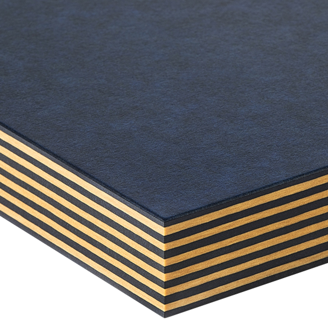
Each box body uses four slabs of 8 inch × 8 inch × 2 inch Richlite phenolic-paper laminate, laminated face-to-face with epoxy into a single 8″ × 8″ × 8″ block, then milled down to a 7.25″ cube. Richlite is the trade name (Adam pronounces it “Rich Lite” but the company spells it as one word) — it’s a paper-and-resin monolithic composite, about 65% FSC paper / 35% phenolic resin by weight, originally developed for industrial tooling and now widely sold as a guitar-fretboard and counter-top material. It machines like a dense hardwood, sands smooth, takes paint perfectly, and produces no nasty dust beyond ordinary phenolic.
Source: Maker Material Supply, Boedeker, or Professional Plastics. Expect ~$30–40 per 2″-thick 12″×12″ slab; cut to 8″×8″ on a table saw before lamination. Two boxes need eight slabs total; budget ~$300 for material.
Adam considered actual magnesium and rejected it on fire-safety grounds: magnesium machining chips burn at very high temperatures and cannot be extinguished with water. Don’t second-guess this. Richlite is genuinely indistinguishable from raw magnesium under paint and isn’t going to set the shop on fire.
2.4.2 §4.2 Lamination and squaring
- Surface prep each slab: face-mill both flat sides on the mill at 0.05 mm DOC, or hand-flatten on a granite plate with 80-grit. The mating surfaces have to be parallel and flat enough that the epoxy joint is uniform.
- Epoxy lamination. Use methylmethacrylate structural adhesive (Loctite SA 9460 or 3M DP8005) — Adam’s choice and the right one for this. Roll on a 0.3 mm bead, clamp the stack overnight under at least 200 lb of dead weight (a couple of bags of lead shot work fine), let it cure 24 hours.
- Face-mill the cube down to 7.25″ on a side. Adam’s procedure: 8″ stock to 7.25″ means 0.375″ comes off each face. Mark out a cut at 2.625″ from the bottom edge of the 8″ stock; that gives a 1/3-up split line at 2.42″ in the finished 7.25″ cube (within 0.005″ of the original geometry). All six sides must be square and parallel to each other before the cavity work begins.
2.4.3 §4.3 Sphere cavity
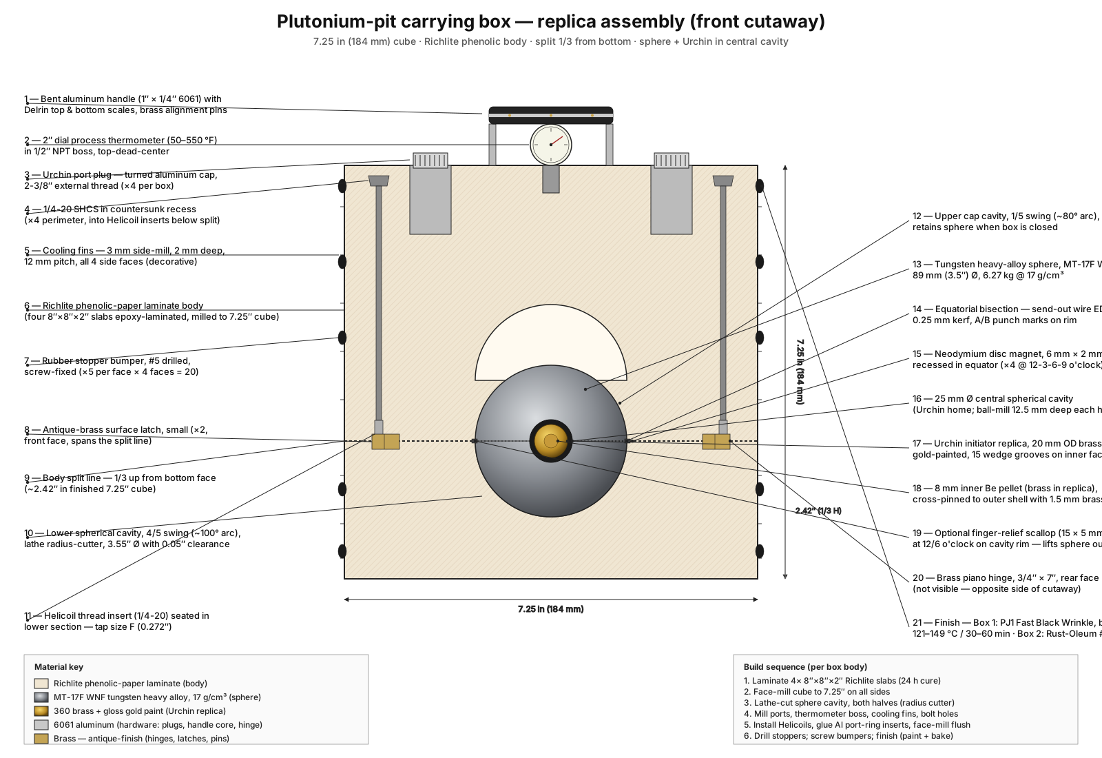
This is the lathe operation that defines the build. The sphere has to seat with the seam between hemispheres exactly on the box’s horizontal split line, and the box has to lift open without the sphere falling out — meaning the lower cavity has to be slightly more than half-spherical (Adam’s 4/5 / 1/5 ratio) and the upper cavity has to be the complementary 1/5 cap.
The reference number on the sphere is critical. Measure your actual sphere’s diameter with a surface gauge before machining — Adam’s was within 100 microns of 3.500 inches; yours may vary by ±0.005″ depending on MT’s centerless grind. Use that measured diameter, plus 50-thou clearance, as the cavity diameter: target 3.55″ Ø spherical pocket in the lower box section.
Procedure:
- Chuck the bottom box section in a 6-jaw chuck on the lathe, with the to-be-cavity face out. Center it on the lathe spindle to within 0.05 mm (indicate the four side faces).
- Set up the radius cutter. Adam used a single-point radius cutter — a yolk with a swiveling cross-slide that swings a single tool around an arc. The setup measure-of-record is the distance from the yolk’s machined flat to the tool tip, which equals the radius being cut, minus a known offset (Adam’s was 0.5″). For a 3.55″ Ø cavity, the radius is 1.775″; minus the 0.5″ yolk offset, the tool tip should sit 1.275″ from the yolk’s flat. Use two gauge-block stacks at 1.275″ as a depth check before any chip is cut.
- Test cut in scrap (a piece of 6061 aluminum at 8″×8″ works). Confirm the cavity diameter is dead on.
- Cut the cavity in the box bottom. Slow feed, frequent stops to clear chips. The radius cutter swings through about 100° of arc — slightly more than 90° to give the 4/5 / 1/5 split. Final pass at light DOC.
- Chamfer the cavity rim for the upper-cap fitment (small 3 mm × 45° around the cavity mouth — lets the upper cap drop in flush).
- Repeat for the upper box section — but a much shallower swing, only about 80° of arc, producing the 1/5 cap.
When done, dry-fit the sphere. The hemispheres should sit centered with a slight vacuum effect when seated; the upper cap should lift off cleanly. Adam noted his cap was “an eighth of an inch too tall” on first fit — a chamfer relief inside the cavity rim fixed it. Be ready to make that adjustment.
2.4.4 §4.4 Bolt holes and Helicoils
Four 1/4-20 socket-head cap screws run from the top of the upper section down into threaded inserts in the bottom section, one centered on each side, holding the box closed. The screws sit in counter-sunk recesses; measure your counter-sinks to match each other — this is the Adam-emphasized “looks-like-it-was-manufactured-by-the-military” detail. A counter-sink stop-collar on the drill helps.
Bolts pass through clearance holes in the upper section, into helicoiled threads in the bottom section. Tap procedure: 1/4-20 helicoil tap drill is 0.272″ (size F). Tap by hand from inside the cavity outward — easier to keep the tap perpendicular that way. Replace the tap as soon as it shows any drag; tungsten alloy is forgiving, Richlite phenolic is not. Adam broke one tap on his build and recovered with extraction pliers and a backup helicoil; allow for one breakage.
2.4.5 §4.5 Decorative cooling fins
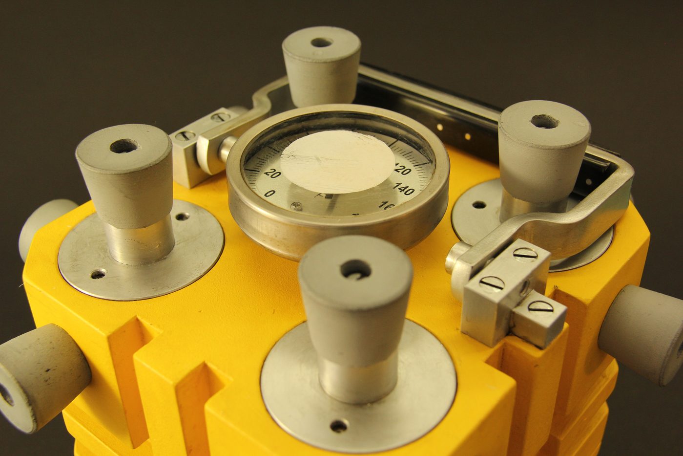
The original boxes had horizontal fins machined into the four side faces — visible cooling fins that increased surface area to dissipate the warmth of the (radioactively self-heating) pit inside. Adam reproduces these on the Tested build; they’re prominent in the Case1/Case2/Case3 reference photographs.
Cut on the mill with a 3 mm side mill: parallel grooves 2 mm deep, 12 mm pitch, running horizontally across each side face. Six grooves per face, three above the split line, three below (or however many fit cleanly with the bolt counter-sunks). The fins do not have to be visually perfect — they’re aged-factory-finish detail — but they have to be parallel and the same pitch on all four faces.
2.5 §5 Hardware — the Adam suite
2.5.1 §5.1 Urchin port plugs (×4 per box, ×8 total)
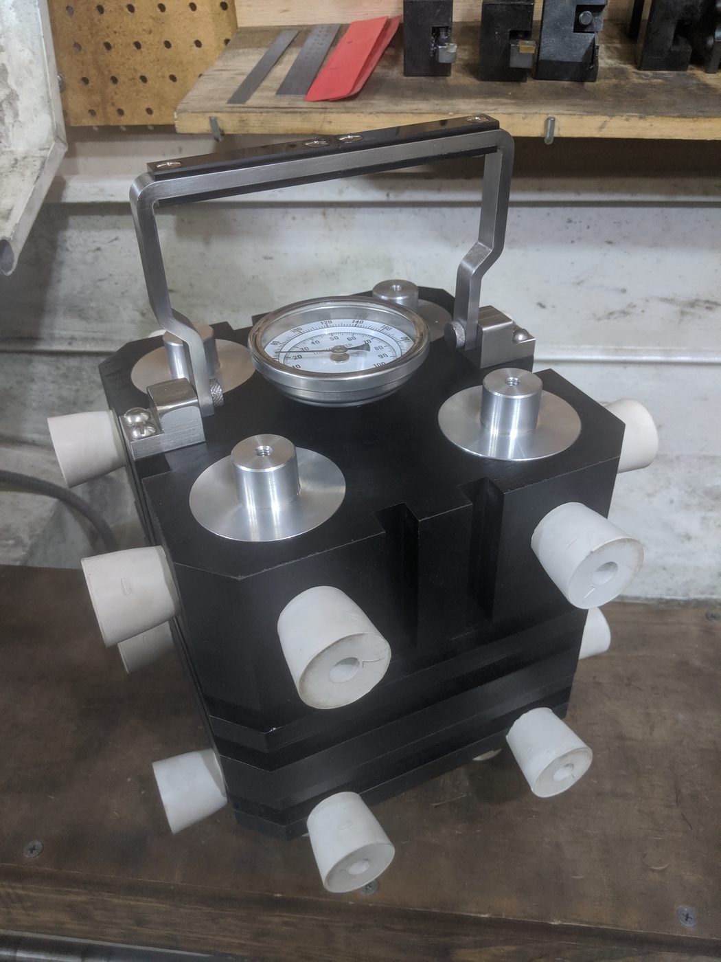
The original boxes had four ports on the top face — corner-positioned, internally threaded with a 2-3/8″ machine thread — to hold up to four spare Urchin initiators in transit. Each port had a screw-in plug with a flush cap above the surface. Adam reproduces the geometry by milling the ports into the Richlite top, gluing in aluminum threaded rings as inserts (because aluminum threads more reliably than Richlite), and turning aluminum plugs with matching outer threads to screw into them.
Procedure (per port, ×4 per box):
- Bore the port through the top of the upper box section. Adam used a Forstner bit for rough material removal and a 2″ annular cutter for the final pass; either works. Bore depth ≈ 1.5″.
- Turn the aluminum ring. From a chunk of 2.5″ Al rod, internal-thread a 2-3/8″ ID with a single-point threading tool. Part off five rings, each ~0.5″ tall — four to install plus one spare (Adam’s lesson: cut more thread than you think you need, you can’t come back for it cheaply).
- Glue the rings into the bores with CA glue. Press-fit if possible; the rings should sit just-proud of the top surface, ready to be face-milled flush.
- Turn the plug caps from 1″ Al rod. Each cap is ~1″ Ø × 0.675″ tall, with external 2-3/8″ threads at the bottom that mate to the ring threads, and a knurled grip on top. Cut spanner-wrench holes at 180° in the cap face (a #29 drill, 0.136″ Ø, on a 0.75″ bolt-circle) — these are what you’d use to install or remove the plug. Don’t add a screwdriver slot; the originals didn’t have them.
- Face-mill the top surface with the rings glued in. A skim pass with a 3″ face mill produces a single flat surface where the rings disappear into the Richlite under paint — the optical illusion that this whole thing is one piece of silver metal.
Adam’s quote on this section: “They will just look black with an internal thread… and you won’t see the seams. It’ll just like this look like this whole thing’s made out of some silver metal. That’s the optical illusion.” That’s the goal.
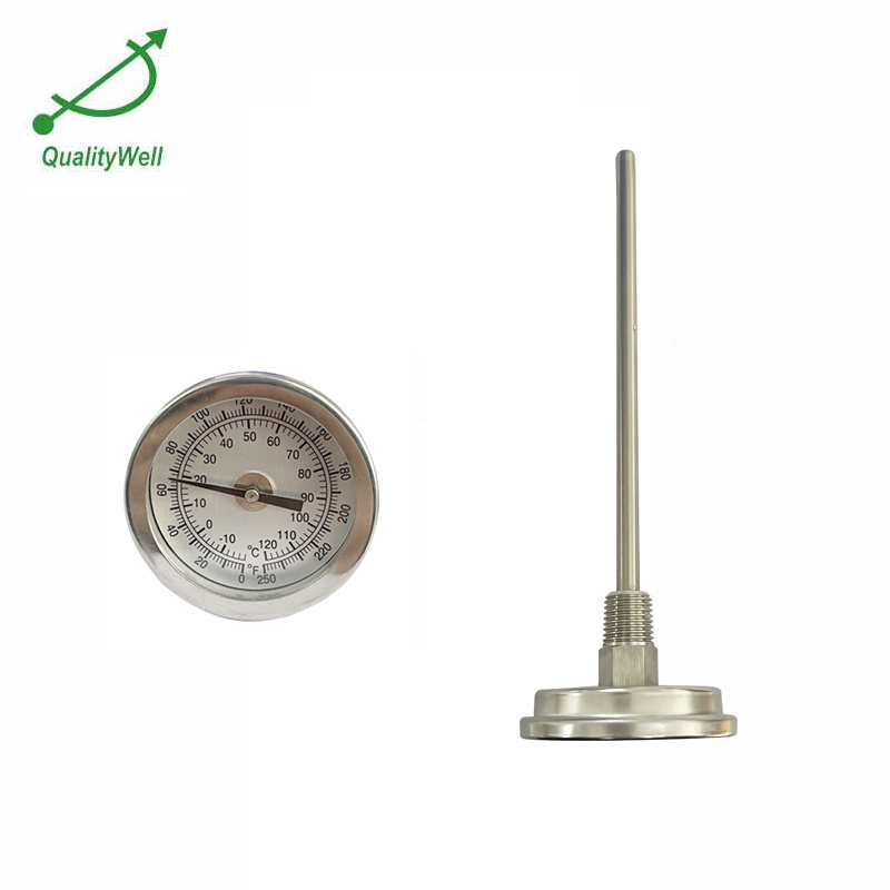
2.5.2 §5.2 Thermometer
Top-dead-center on each box, a 2″-diameter process thermometer sits in a 1/2″ NPT boss. Adam’s source was generic industrial-supply; McMaster part #3825K58 (2″ dial, stem 4″, 1/2″ NPT, 50°–550° F range) is a $25 close match. The thermometer is drilled into the cavity-side of the upper section as part of the lathe setup that did the cavity — easier to drill it while the box is still chucked on the lathe.
The thermometer doesn’t have to read accurately. It has to look like the original equipment. A vintage-look dial face from a salvage motorcycle thermometer is even better.
2.5.3 §5.3 Handle
The handle is a bent aluminum bar with a Delrin grip held by brass alignment pins, made like a knife handle. Stock: 1″ × 0.25″ × 12″ 6061 aluminum, bent into a U-shape with a 4″ inside grip width, mounted to the box’s top face with two 1/4-20 SHCS into helicoiled threads at the corners.
The grip section gets a Delrin scale on top and bottom, sandwiching the aluminum bar. Each scale is 1″ × 0.5″ × 4″, with the aluminum bar’s profile traced and the Delrin milled to a 0.005″ undersize so the aluminum sits proud (visible silver line between the black Delrin scales). Three brass alignment pins (0.125″ Ø) pass through both scales and the aluminum core; epoxy holds the whole assembly. Adam’s quote: “I’m making it like I’m making a knife.”
After assembly, file or sand the edges of the Delrin to soft curves where the hand grips it. A handle that doesn’t hurt the hand to pick up a 14-lb box is a non-negotiable detail.
2.5.4 §5.4 Latches and hinge
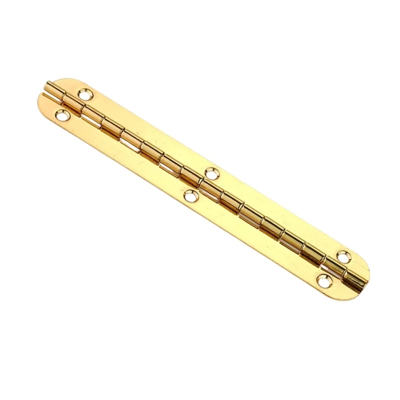
- Hinge: continuous brass piano hinge, 0.75″ × 7″, mounted to the rear face spanning the horizontal split line. Source: Rockler #43855 or any brass piano-hinge in inventory.
- Latches: two small antique-brass surface latches on the front face, also spanning the split line. Source: Lee Valley #00W3905 or any small brass case latch ($10–15 each). These are visible on Replica 4’s detail photo and on Adam’s black-crackle build.
The latches are functional — they hold the box closed in transit. The four perimeter bolts are also functional but are typically left tightened. For day-to-day display use, the latches do the work.
2.5.5 §5.5 Rubber-stopper bumpers (×20 per box, ×40 total)
The shock-absorption system on the originals was rubber test-tube stoppers — specifically, #5 size (or thereabouts; the originals were salvage from the chemistry lab) — drilled through the center, screwed to the box body with a counter-sunk wood screw. Twenty stoppers per box: five per side × four sides (top and bottom are clear except for the hardware suite).
Source: any laboratory supply house. Modern equivalent is Plasticoid #5 black rubber stopper, drilled — $0.40 each on Amazon, $8 total per box.
Installation procedure (Adam’s hard-learned hardware step):
- Drill the stopper. Adam’s first plan was to chuck the stoppers in the lathe after dipping them in liquid nitrogen, on the theory that rubber turns hard when frozen and could be drilled like Delrin. You don’t need the liquid nitrogen. Adam discovered mid-build that a sharp #7 drill bit drills room-temperature rubber stoppers cleanly. Skip the LN2.
- Drill the stopper through the center axis, #7 (0.201″) drill. The hole is for the wood screw.
- Drill the box body at the stopper location for a clearance pilot, then drive a #8 × 1″ counter-sunk Phillips wood screw through the stopper into the body. Snug, not tight — the screw should pull the stopper flat against the box but not deform the rubber.
- Plug the screw head with a small black rubber dot or just leave the slot visible (originals had visible slots).
Twenty stoppers per box × two boxes = forty stoppers. Buy 50 — Adam notes some will fail and you’ll want spares.
2.6 §6 Finish — two parallel paths
This is the only section where the two boxes diverge.
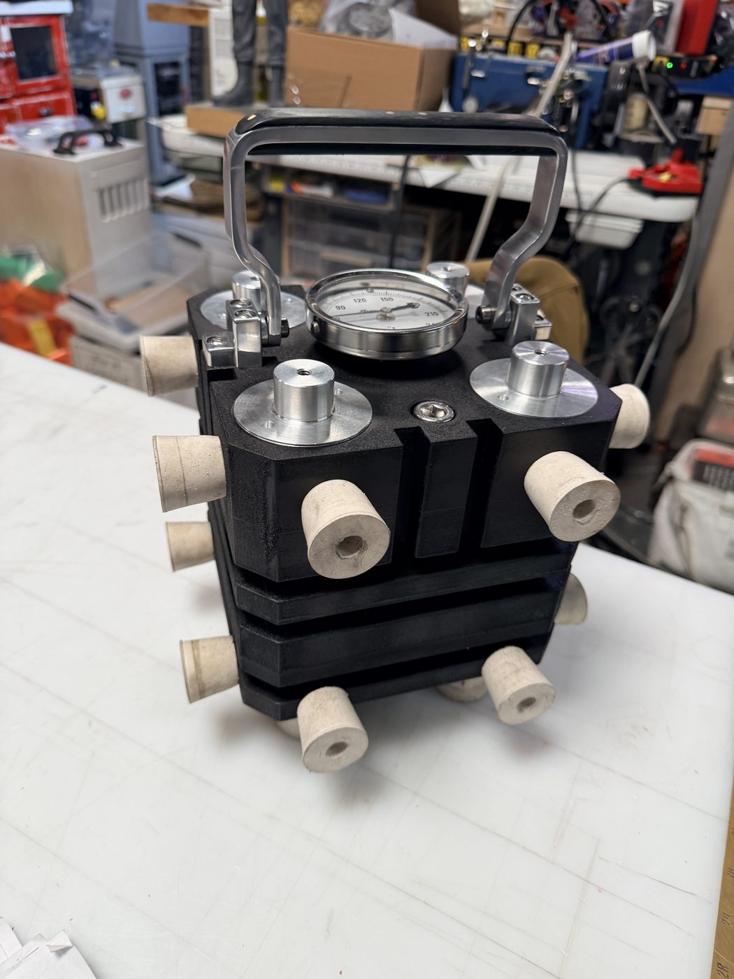
2.6.1 §6A Box 1 — Black crackle (Trinity gadget-core style, Adam-exact)
The only one of the three original boxes with documented color information is the Trinity gadget-core box: chemically etched to a dull black finish that obscured the magnesium’s natural silver-grey. Adam recreates this with PJ1 motorcycle paint.
- Surface prep. Sand all Richlite surfaces (and the aluminum hardware that’s getting painted with the body) to 320 grit. Wipe with denatured alcohol; let dry 10 minutes.
- Gloss-black base coat. Two light coats of Rust-Oleum Specialty High-Heat Gloss Black (or any 500°F-rated gloss black engine enamel — the crackle paint needs a heat-tolerant base because of the bake step). Re-coat at 5 minutes; cure 24 hours.
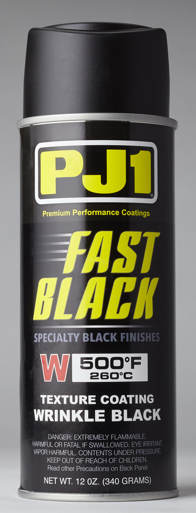
- Crackle topcoat. PJ1 Fast Black Wrinkle/Texture spray paint, motorcycle-supply (Witchdoctors, RevZilla, ~$15/can). Two light coats applied 3 minutes apart, per the can label. Don’t overdo it — too thick produces shallow crackle; too thin produces no crackle. Test on scrap first.
- Bake. 30–60 minutes at 121–149 °C (250–300 °F) in a dedicated paint oven or toaster oven (don’t use a kitchen oven). The crackle develops during the bake — the underlying solvent flashes off through the top film, creating the wrinkle. Adam quoted “125 to 150 for about an hour” — note the units are Celsius, matching PJ1’s spec.
- Cool slowly to room temperature. Inspect for thin spots or sags; touch up with a single light overspray and re-bake the spot.
Result: the deep textured black-on-black finish visible in the Case1/Case2/Case3 reference photographs and on Adam’s Tested episode.
2.6.2 §6B Box 2 — Zinc-chromate yellow (Fat Man style, Sackett 2017 reference)
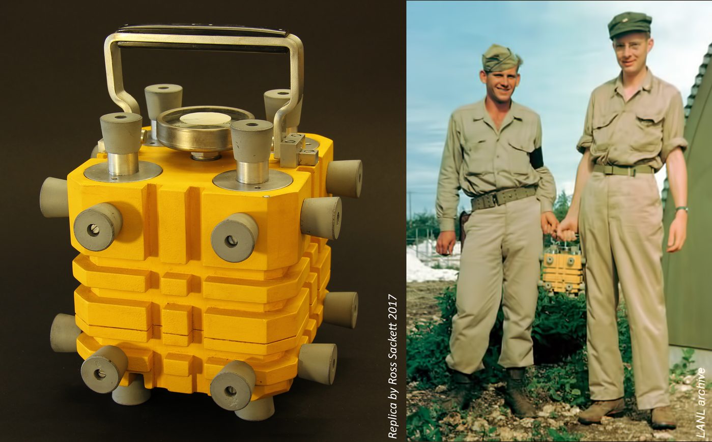
The Fat Man box that traveled to Tinian was painted with the same mustard-yellow zinc-chromate primer used on the bomb casing itself — “school-bus yellow” with an olive shift. The only color photograph of the original is the Agnew/Tinian image (see Vol 1 §5.2 or the figure below). Ross Sackett’s 2017 prop-shop replica (Replica 2, 3, 4 reference photos) is the closest open-source visual match.
- Surface prep. Same as Box 1 — 320 grit, alcohol wipe.
- Filler primer. Grey automotive filler primer (Rust-Oleum Filler Primer or Eastwood Self-Etching Primer). Two coats wet-sanded to 400 grit. Goal: dead-flat surface; the yellow shows every imperfection.
- Color coat. Rust-Oleum Specialty Industrial Choice Safety Yellow (#1644 — the “school-bus” hue) — two medium coats, 15 minutes apart, full cure 24 hours.
- For a slightly more olive zinc-chromate match, dust a fourth-coat of Rust-Oleum Industrial Olive Drab at ~10% coverage just before the final cure. The original zinc-chromate primer had a slight olive cast that pure school-bus yellow lacks.
- Optional weathering. A light brown enamel wash in the recesses (around the bumpers, in the fin grooves) with a 50/50 mineral-spirits/burnt-umber thinned wash — suggests 80 years of handling without overdoing it. Tamiya Weathering Master Set B “Mud” brushed lightly into the same areas is faster.
- Topcoat. Two coats of satin clear lacquer (Rust-Oleum Clear Satin) — protects the yellow and locks in the weathering. No baking required.
Result: the mustard-yellow finish of the Agnew Tinian box and the Sackett 2017 replica.
2.6.3 §6C Optional — accelerated aging (both boxes)
If the replicas look “too new” after painting, add a light dry-brush of warm grey acrylic along the fin grooves and around the handle base — picks out the high points, suggests wear. Tamiya Weathering Master Set B is the standard tool here. Don’t overdo it; the originals were not abused.
2.7 §7 Interior and display
2.7.1 §7.1 Interior cradle
The sphere sits in the lower box’s hemispherical cavity by gravity. No foam, no padding — the cavity itself is the cradle, and the 4/5 / 1/5 cap geometry of the upper section holds the sphere captive when the box is closed. This is Adam’s solution and it works.
For ease of removal, machine two opposing shallow finger reliefs into the cavity rim — small 15 mm-wide × 5 mm-deep half-moon scallops at the 12 o’clock and 6 o’clock positions, just below the split line. They let you slip a fingernail under the sphere and lift it out without surgery. The originals didn’t have these (the assembly crew used spring-loaded grips); the build does.
2.7.2 §7.2 LANL property tag
Each box gets a paper label inside the upper lid — cream-colored cardstock, black serif type (a Caslon or Garamond cut suits 1945), modeled on the actual LANL property-tag style of the period. Fields:
LOS ALAMOS SCIENTIFIC LABORATORY
PROPERTY TAG
————————————————————
MATERIAL:    Pu-239 (delta-phase Pu-Ga, 0.8% Ga)
WEIGHT:      6.2 kg ± 0.05
DIAMETER:    8.9 cm
INSPECTOR:   HKD / LAS
SERIAL:      1945-003
————————————————————
SECRET — Handle Under Q Clearance Only
The HKD/LAS inspector initials honor Harry K. Daghlian Jr. and Louis A. Slotin — a quiet memorial inside the closed box. Print on cream-toned text-weight paper; mount with a single drop of CA glue at each corner. PDF template will live at 04-templates/property_tag.pdf once finalized.
2.7.3 §7.3 Display arrangement
Single-box display: closed box on shelf, museum-caption card alongside. Sample card text:
Replica of the magnesium plutonium-pit carrying box designed by Philip Morrison and machined by Ralph C. Sparks at Los Alamos in 1945. The contained sphere represents the third pit cast for the Manhattan Project — codenamed “Rufus,” later “the demon core” — the cause of the August 1945 and May 1946 criticality accidents that killed Harry K. Daghlian Jr. and Louis A. Slotin. The original pit was melted down in the summer of 1946; this replica is non-radioactive tungsten heavy alloy at the original 6.2 kg mass.
Two-box display: black-crackle and yellow boxes side by side on a long shelf, both closed. The bisected sphere with the Urchin nested in its cavity sits between them as a separate “exploded view” demonstration — split halves with the Urchin centered between them. A small placard under each box names its provenance (gadget-core / Fat-Man).
This is the museum-quality display Adam’s friend Kyle Hill called out as “dude, that’s museum quality.”
2.8 §8 Bill of materials
Table 2 — §8 Bill of materials
| Item | Qty | Source | Per | Subtotal |
|---|---|---|---|---|
| Pit | ||||
| MT-17F WNF tungsten heavy-alloy sphere, 3.5″ Ø custom | 1 | Midwest Tungsten Service (custom-quote) | $1,300 | $1,300 |
| Wire-EDM bisection + fixturing | 1 | Local job shop | $250 | $250 |
| 25 mm Ø carbide ball-end mill | 1 | McMaster #2841A75 or equivalent | $80 | $80 |
| 6 mm × 2 mm neodymium discs | 4 | K&J Magnetics | $1 | $4 |
| Urchin | ||||
| 360-brass round, 25 mm × 6″ | 1 | Online Metals | $20 | $20 |
| 8 mm brass ball (drilled) | 1 | Online Metals | $4 | $4 |
| Brass pin stock, 1.5 mm × 12″ | 1 | Online Metals | $6 | $6 |
| Testor’s metallic gold gloss + masking fluid | 1 | Hobby store | $10 | $10 |
| Box bodies (×2) | ||||
| Richlite, 8″×8″×2″ slab | 8 | Maker Material Supply | $40 | $320 |
| Loctite SA 9460 methacrylate adhesive | 1 | McMaster | $35 | $35 |
| 1/4-20 SHCS, 6″, 18-8 SS | 8 | McMaster | $4 | $32 |
| 1/4-20 helicoil installation kit | 1 | McMaster #91732A180 | $50 | $50 |
| Hardware (×2 each unless noted) | ||||
| Aluminum rod, 2.5″ × 12″ (urchin port rings) | 1 | Online Metals | $40 | $40 |
| Aluminum rod, 1″ × 24″ (urchin port plugs + handle) | 1 | Online Metals | $30 | $30 |
| Process thermometer, 2″ dial, 1/2″ NPT | 2 | McMaster #3825K58 | $25 | $50 |
| Delrin block, 1″ × 1″ × 8″ (handle scales) | 1 | Online Metals | $30 | $30 |
| Brass piano hinge, 0.75″ × 7″ | 2 | Rockler #43855 | $15 | $30 |
| Antique-brass surface latch, small | 4 | Lee Valley #00W3905 | $12 | $48 |
| Black rubber stopper, #5, drilled | 50 | Plasticoid via Amazon | $0.40 | $20 |
| #8 × 1″ countersunk wood screws | 50 | McMaster | $0.10 | $5 |
| Finish — Box 1 black crackle | ||||
| Rust-Oleum High-Heat Gloss Black | 1 | Home Depot | $10 | $10 |
| PJ1 Fast Black Wrinkle paint, 12 oz | 2 | Witchdoctors | $15 | $30 |
| Finish — Box 2 yellow | ||||
| Rust-Oleum Filler Primer, grey | 1 | Home Depot | $10 | $10 |
| Rust-Oleum Industrial Choice Safety Yellow #1644 | 2 | Home Depot | $10 | $20 |
| Rust-Oleum Industrial Olive Drab (dust coat) | 1 | Home Depot | $10 | $10 |
| Rust-Oleum Clear Satin lacquer | 1 | Home Depot | $10 | $10 |
| Tamiya Weathering Master Set B (Mud) | 1 | Hobby store | $15 | $15 |
| Subtotal — materials | $2,469 | |||
| Optional: electroless Ni plating on sphere (post-build) | 1 | Local plating shop | $120 | $120 |
| Grand total with plating | ~$2,589 |
The single biggest variable is the sphere itself ($1,300 estimate; could come back from MT’s custom quote anywhere from $1,000 to $1,800 depending on their current tungsten input cost and lead time). Get the quote first; the rest of the BOM scales linearly with how many boxes you actually decide to build (one box drops the budget to ~$1,800 total).
2.9 §9 Build order and time estimate
Approximate sequence and shop time, for two boxes built in parallel:
- Order sphere + Richlite — wait 6–8 weeks for MT, 1 week for Richlite. (Order day 1.)
- Lamination of both 8″ blocks — 2 hours of work + 24-hour cure. (Week 1.)
- Face-mill both blocks to 7.25″ cubes — 4 hours mill time. (Week 1–2.)
- Sphere arrives — measure, then send for wire-EDM bisection (1-week turnaround at job shop). (Week 7.)
- Cavity machining in both box bodies (lathe radius cutter) — full day each, 2 days total. (Week 7.)
- Urchin replica fabrication — 1 full day at the lathe and mill. (Week 7.)
- Sphere returns from EDM — Urchin cavity machining on the mill, magnet recess work, dry-fit. (Week 8.)
- Urchin port machining + glue-up — 1 full day per box. (Week 8.)
- Cooling fins, bolt holes, thermometer boss — 1 full day per box. (Week 9.)
- Hardware fabrication (handle, latches install) — 1 full day per box. (Week 9.)
- Stopper installation — 4 hours total (40 stoppers). (Week 10.)
- Box 1 — black crackle finish + bake — 2 days including cure. (Week 10.)
- Box 2 — yellow finish + weathering — 2 days including cure. (Week 10–11.)
- Final assembly + property tags + display setup — 1 day. (Week 11.)
Total: about 8–10 weekends of shop time spread across 10–11 calendar weeks, gated mostly by the sphere lead time. Adam’s Tested version was a “three-day build” because he had the sphere already in hand, did one box only, and skipped both the bisection and the Urchin.
2.10 §10 Budget appendix — abbreviated lighter-weight paths
For anyone reading this for whom $2,500 is not the right number, three alternative build paths from the previous version of this volume are preserved below. None of them produce a museum-quality replica; all of them produce something credible on a shelf at home.
Path α — 3D-printed PLA sphere + 3D-printed PLA box. Print Printables #1390266 (sphere) and #451707 (case), assemble, paint chrome on the sphere and zinc-chromate yellow on the case. ~$80 total. No metal sphere heft. No split-pit. Fine for a Halloween prop, weak for display.
Path β — Plywood box + lead-shot-weighted resin sphere. Box-jointed 12 mm Baltic birch case with the same hinge/latch/bumper hardware as the Richlite build; sphere cast in two halves of black-pigmented epoxy resin loaded with lead shot, totaling ~5.6 kg. Looks credible at conversational distance; doesn’t survive close inspection. ~$300 total. Good middle-ground option.
Path γ — Wood box + steel ball-bearing sphere. A 3.5″ Ø chrome-steel ball bearing from McMaster (#9529K78, ~$120) at 3.62 kg lives in a plywood Adam-clone case. The mass is short of the original by about half, but the chrome ball-bearing looks the part exactly. ~$400 total.
These are documented for completeness. The default build is now the Adam-faithful two-box pair described in §1–§9 above.
2.11 §11 What’s left for the next revision
- Photograph the actual build as it progresses; replace all reference-photo figures in §1, §4, §5, §6 with own work in
02-inputs/deep_dive/figs/build_*(raw sphere, split sphere, urchin in cavity, lamination, finished black box, finished yellow box, two-box display). - Confirm MT-17F custom-quote pricing with Midwest Tungsten Service and pin the exact lead time. Update §2.1 and §8.
- Settle on the LANL property-tag artwork and produce
04-templates/property_tag.pdffrom a vector master. - Document the actual radius cutter setup numbers for the box cavity, including any required adjustments to the gauge-block math, once the cavity is cut.
- Refine the Urchin gold/nickel finish by paint-test comparison against the Wikipedia Urchin article’s photographs.
References
Build references
- “Adam Savage Builds a Demon Core!” Tested YouTube, 2024 — https://www.youtube.com/watch?v=V1Y4UR8xqxA (full transcript on file at
02-inputs/Adam Savage Youtube Build Transcript.txt) - “The plutonium box” — Alex Wellerstein, Restricted Data, 2014-03-28 — https://blog.nuclearsecrecy.com/2014/03/28/plutonium-box/
- “Harold Agnew carrying the plutonium core, Nagasaki Fat Man bomb, 1945” — Rare Historical Photos — https://rarehistoricalphotos.com/harold-agnew-carrying-plutonium-core-nagasaki-fat-man-bomb-1945/
- Sparks, Ralph C. Twilight Time: A Soldier’s Role in the Manhattan Project at Los Alamos. Los Alamos Historical Society, 2000.
- Attoparsec, “Manhattan Project plutonium box” — https://www.attoparsec.com/artifacts/plutonium.html
- Sackett, Ross — “Historical prop: The plutonium carrying box for the Fat Man bomb” RPF — https://www.therpf.com/forums/threads/historical-prop-the-plutonium-carrying-box-for-the-fat-man-bomb.278641/
- FuzzyRaptor, Printables #451707 (plutonium core case) — https://www.printables.com/model/451707-plutonium-core-case
- blackrat, Printables #1390266 (demon core sphere) — https://www.printables.com/model/1390266-demon-core-replica-full-scale-scaled-3d-print
Material and tooling
- Richlite — Richlite Company, https://www.richlite.com/ ; retail at Maker Material Supply, Boedeker, Professional Plastics
- Midwest Tungsten Service — https://shop.tungsten.com/ ; [email protected] for custom quotes
- MT-17F WNF alloy technical data — https://www.tungsten.com/material-info/tungsten-heavy-alloy-w-ni-fe-cu
- PJ1 Fast Black Wrinkle paint — https://pj1.com/product/fast-black-texture-paint/
- Lansing Lamont, Day of Trinity (Atheneum, 1965) — source of the pit cross-section illustration
Historical references (carried forward from Vol 1)
- “Demon core” — Wikipedia — https://en.wikipedia.org/wiki/Demon_core
- “Pit (nuclear weapon)” — Wikipedia — https://en.wikipedia.org/wiki/Pit_(nuclear_weapon)
- “Urchin (detonator)” — Wikipedia — https://en.wikipedia.org/wiki/Urchin_(detonator)
- Granowitz, “Medical Studies of the Demon Core Victims,” Stanford PH241 (2024) — http://large.stanford.edu/courses/2024/ph241/granowitz2/
Cross-reference
- Vol 1 — The Demon Core: A History —
./vol1.md
Comments (0)